
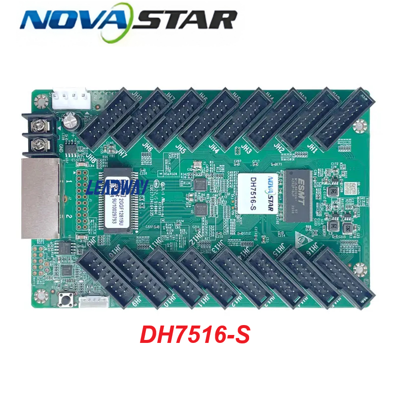


NV7516s Novastar Receiving Card
The NovaStar DH7516-S is a general-purpose receiving card developed by Xi’an NovaStar Tech Co., Ltd. for full-color LED displays. It integrates physical hardware connectors with data processing mechanics to decode incoming control commands and pixel matrix streams. Designed with 16 standard HUB75E interfaces, the card ensures stable serial communication across an array of on-site configurations.
The DH7516-S balances image fidelity, maintainability, and structural reliability, featuring point-by-point pixel calibration, onboard telemetry diagnostics, and systemic program failovers. This makes it highly compatible with modern LED panel cabinets deployed in commercial signage, live entertainment stages, and fixed permanent indoor or outdoor installations.
Technical Specifications & Features
Core Display Capabilities & Scaling Limits
-
Maximum Loading Capacity: Resolution capabilities depend heavily on the driver chip architecture built into the LED panel:
-
PWM Driver ICs: Supports high-resolution grids up to $512\times384$ @ 60Hz per card.
-
Common Driver ICs: Supports standard resolution grids up to $384\times384$ @ 60Hz per card.
-
-
Parallel Color Processing: Natively manages up to 32 groups of parallel RGB data paths to streamline video execution and refresh loops.
-
Compliance Certifications: Officially certified under RoHS and EMC Class A regulatory parameters.
Advanced Visual Enhancements
-
Point-by-Point Brightness Calibration: Works alongside NovaStar’s high-precision calibration software to fine-tune individual light pixel levels, eliminating brightness variance across panels to ensure screen-wide uniformity.
-
Quick Line Adjustments: Accelerates the tracking and correction of bright or dark seams generated by manual physical alignment errors when module cabinets are spliced together, taking effect immediately.
-
3D Mode Synchronization: Interoperates with specialized master video controllers possessing 3D processing features to output stereoscopic 3D images.
-
Independent RGB Gamma Tuning: When linked with a compatible controller and running NovaLCT version V5.2.0 or later, the Red, Green, and Blue Gamma curves can be adjusted independently. This counters low-grayscale non-uniformity and white-balance drift, creating realistic imagery.
-
Incremental 90° Picture Rotation: Allows full-screen display adjustments by turning the output graphic layout in exact 90° steps ($0^\circ / 90^\circ / 180^\circ / 270^\circ$).
Smart Maintainability & Diagnostics
-
Intelligent Mapping Function: Automatically pushes identification markers—including the specific LED master controller index number, individual receiving card number, and connected Ethernet port topology lines—directly onto the physical cabinets. This allows onsite technicians to easily trace network signal layouts.
-
Pre-Stored Placeholder Images: Allows operators to establish a customized graphic to display on the panel during initial system startup, or as a failback screen if an Ethernet line disconnects or an external input video feed drops completely.
-
Onboard Sensor Telemetry: Constantly tracks internal hardware operating voltage and ambient board temperatures in real time without needing external peripheral sensors.
-
Cabinet LCD Interface Mapping: Feeds real-time tracking data directly to external cabinet-embedded LCD modules, displaying current voltage, temperature, single run duration, and total combined lifetime operating hours.
-
Network Bit Error Monitoring: Routinely monitors the underlying communication quality across active Ethernet ports, logging erroneous data packets to help isolate and troubleshoot signal faults.
-
Data Registers & Firmware Flash Readback: Configuration parameter settings and core firmware programs stored directly inside the card can be read back and saved locally to a computer file.
System Reliability & Redundancy
-
Dual-Cable Loop Backup: Allows primary input and secondary backup cable connections to form a secure loop back to the sending infrastructure. If a break occurs along the network path, the backup line keeps the panel displaying frames without a visual glitch.
-
Dual Program Boot Failover: Outfitted with two complete copies of the internal operational firmware program at the factory. If a remote online upgrade faces a power disruption or falls into an error loop, the device switches over to its backup safety layer to prevent locking up or “bricking”.
Data Reference Tables
Hardware Components Layout & Interfaces
The DH7516-S breaks down into specific physical component interfaces distributed across the board layout:
| Interface Port Label | Physical Description & Purpose |
| HUB75E Connectors | 16 standard onboard male connectors distributed symmetrically on the Left and Right wings to route parallel RGB data to the LED modules. |
| Power Connectors | Multiple input sockets located on the bottom-left edge to distribute incoming DC power; technicians can choose either socket to power the board. |
| Gigabit Ethernet Ports | Dual ports situated on the bottom edge to communicate with the master controller/sending card or cascade downstream to additional units. Each port accepts arbitrary primary input or backup loop return assignments. |
| Self-Test Button | Tactile micro-switch placed on the bottom right. When an Ethernet link is disconnected, pressing the button twice forces a diagnostic test pattern to load; further presses cycle through patterns. |
| 5-Pin LCD Connector | A small dedicated pin row mapping internal system telemetry to an external cabinet-mounted LCD status panel. |
Diagnostic LED Indicator States
The running conditions of the card are indicated by the color and frequency of the diagnostic lights on the board:
| Indicator Name | Emitted Color | Flashing Status / Interval | Current Operational Meaning |
| Running Indicator | Green | Flashing once every 1s | Normal functionality: network link is stable, and a live input video feed is detected. |
| Green | Flashing once every 3s | Network error: physical Ethernet cable connection is abnormal or broken. | |
| Green | Flashing 3 times every 0.5s | Partial signal: network cable link is healthy, but no external input video source is available. | |
| Green | Flashing once every 0.2s | Core application firmware failed to load; safe backup program is automatically active. | |
| Green | Flashing 8 times every 0.5s | Redundancy switchover has occurred on the network loop; active backup link is handling data paths. | |
| Power Indicator | Red | Always on (Solid State) | Main DC power supply distribution to the board components is stable and normal. |
Pin Definitions (HUB75E Interface – JH1 Example)
Each of the 16 standard HUB75E interfaces built into the DH7516-S can route parallel data groups. Taking interface JH1 as a baseline example, the signal mapping of the 16 pins is defined as follows:
| Pin Number | Signal Assignment | Functional Connection Description |
| 1 | R1 | Red Data Channel 1 |
| 2 | G1 | Green Data Channel 1 |
| 3 | B1 | Blue Data Channel 1 |
| 4 | GND | Signal Ground Common Connection |
| 5 | R2 | Red Data Channel 2 |
| 6 | G2 | Green Data Channel 2 |
| 7 | B2 | Blue Data Channel 2 |
| 8 | HE1 | Line Decoding Signal (E-Signal) |
| 9 | HA1 | Line Decoding Signal (A-Signal) |
| 10 | HB1 | Line Decoding Signal (B-Signal) |
| 11 | HC1 | Line Decoding Signal (C-Signal) |
| 12 | HD1 | Line Decoding Signal (D-Signal) |
| 13 | HDCLK1 | Shift Clock Frequency Signal |
| 14 | HLAT1 | Latch Control Data Signal |
| 15 | HOE1 | Display Output Enable Gating Signal |
| 16 | GND | Signal Ground Common Connection |
Physical, Environmental & Electrical Parameters
-
Chassis Outer Dimensions: $145.7\text{ mm} \times 91.5\text{ mm} \times 18.3\text{ mm}$ (Manufacturing tolerance variance: $\pm0.3\text{ mm}$).
-
Board Form-Factor Thickness Limits: Individual component circuit board thickness measures $\le 2.0\text{ mm}$. The aggregate depth (including component profile clearances on both top and bottom layers) measures $\le 19.0\text{ mm}$.
-
Net Unit Weight: 100.9 g (Weight evaluates an isolated single card board module).
-
Electrical Power Inputs: DC 3.8 V to 5.5 V.
-
Rated Operational Current: 0.5 A.
-
Active Hardware Power Draw: Rated at 2.5 W (Actual current draw and power profiles vary depending on module settings and environment conditions).
-
Temperature Operational Limits:
-
Active Operating Range: $-20^\circ\text{C}$ to $+70^\circ\text{C}$.
-
Inactive Storage Range: $-25^\circ\text{C}$ to $+125^\circ\text{C}$.
-
-
Humidity Operational Limits:
-
Active Operating Range: 10% to 90% RH, non-condensing relative thresholds.
-
Inactive Storage Range: 0% to 95% RH, non-condensing relative thresholds.
-
-
Standard Industrial Packaging Layout: Individual units are nested inside protective anti-static blister packs. Standard wholesale cardboard shipping cartons contain exactly 100 receiving cards. The external master box measures $625.0\text{ mm} \times 180.0\text{ mm} \times 470.0\text{ mm}$.

