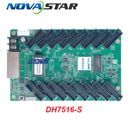
NV7512s Novastar Receiving Card
The NovaStar DH7512-S is a universal, high-performance receiving card developed for managing full-color LED displays. It handles data reception and pixel-matrix rendering directly at the display cabinet level, ensuring stability, image quality, and efficient screen maintenance.
Equipped with comprehensive optimization algorithms, it eliminates visual discrepancies across LED modules and streamlines hardware tracking. The hardware architecture and onboard logic are fully optimized for ease of commercial deployment, multi-screen configuration setups, and smart maintenance routines.
Technical Specifications & Features
Loading Capacity & Matrix Control
-
Pixel Loading Capacity: Supports a maximum resolution of up to $512\times384$ pixels at a 60Hz refresh rate per individual card.
Note: Utilizing full resolution capabilities requires NovaLCT software version V5.3.1 or higher.
Visual Enhancement & Calibration Functionality
-
Color Management: Supports full real-time color management, allowing operators to switch freely between varying display color gamuts to achieve highly accurate color presentation.
-
Point-by-Point Brightness & Chromaticity Calibration: Integrates with NovaStar’s high-precision calibration equipment to fine-tune the color and luminance of every individual LED light point. This eliminates variance across panels to ensure complete screen consistency.
-
Quick Line Alignment: Features instant adjustment mechanics for light and dark seam lines caused by minor physical alignment variations during cabinet or module splicing.
-
Independent RGB Gamma Tuning: Works alongside an independent master controller and NovaLCT (V5.2.0 and above) to adjust Red, Green, and Blue Gamma curves individually. This addresses uneven low-grayscale rendering and white balance drift, producing realistic imagery.
-
3D Output Support: Supports immersive 3D stereoscopic image outputs when linked to an independent sending card outfitted with 3D capabilities.
-
Multi-Directional Picture Rotation: Supports layout orientation adjustments by rotating display graphics in precise 90° multiples ($0^\circ / 90^\circ / 180^\circ / 270^\circ$).
Maintainability & Diagnostic Intelligence
-
Mapping Function Indicator: Displays the distinct receiving card index number and physical network port topology routing maps directly onto the LED cabinet. This provides clarity for onsite technicians troubleshooting signal flow.
-
Pre-Stored Screen Customization: Allows custom pre-stored placeholder imagery to load automatically onto the screen if the configuration computer boots up, the network lines disconnect, or a video input feed drops.
-
Onboard Telemetry & Monitoring: Monitors internal hardware temperature and input voltage levels in real time without requiring external peripheral sensors.
-
Cabinet LCD Interface Capability: Passes tracking metrics—including board temperature, operating voltage, single operation duration, and aggregate lifetime operation hours—directly to external cabinet LCD modules.
-
Network Error Telemetry Log: Performs ongoing quality checks on network communication links, recording error packet volumes to proactively isolate and eliminate signal transmission risks. (Requires NovaLCT V5.2.0 or higher).
-
Data Registers Backup & Readback: Supports reading back and saving both the hardware configuration parameters and the device firmware programs locally to a control computer. (Requires NovaLCT V5.2.0 or higher).
Reliability & Failover Protection
-
Signal Loop Backup Redundancy: Supports dual-cable loop failovers via a primary input and secondary backup cable loop back to the sending card. If a point along the signal wire path fails, the screen continues to display video seamlessly.
-
Dual Boot Firmware Backup: Factory configured with dual firmware application areas. If an online software upgrade fails or suffers a power disruption, the card boots into its backup safety layer to prevent deadlocking or “bricking”.
Data Reference Tables
Hardware Interfaces & Signal Pin Definition (JH1 Example)
The DH7512-S relies on 12 standard onboard HUB75E interfaces for communication, processing up to 24 separate parallel groups of RGB video data paths. Below is the standard pin layout layout configuration:
| Pin Number | Signal Assignment | Functional Description |
| 1 | R1 |
Red Data Channel 1 |
| 2 | G1 |
Green Data Channel 1 |
| 3 | B1 |
Blue Data Channel 1 |
| 4 | GND |
Signal Ground Connection |
| 5 | R2 |
Red Data Channel 2 |
| 6 | G2 |
Green Data Channel 2 |
| 7 | B2 |
Blue Data Channel 2 |
| 8 | HE1 / HE |
Line Decoding Signal |
| 9 | HA1 / HA |
Line Decoding Signal |
| 10 | HB1 / HB |
Line Decoding Signal |
| 11 | HC1 / HC |
Line Decoding Signal |
| 12 | HD1 / HD |
Line Decoding Signal |
| 13 | HDCLK1 / HDCLK |
Shift Clock Frequency |
| 14 | HLAT1 / HLAT |
Latch Control Signal |
| 15 | HOE |
Display Enable Output Gate |
| 16 | GND |
Signal Ground Connection |
Operational Diagnostic Indicator States
| LED Indicator | Emitted Color / State | Flashing Interval | Operational Meaning |
| Running Indicator | Green |
Flashing once every 1 second |
Card is working properly; network cable link is healthy, and an active video input is detected. |
| Green |
Flashing once every 3 seconds |
Network cable link is healthy, but no external video source input is detected. |
|
| Green |
Flashing 3 times at 0.5s intervals |
Network cable link is healthy, but no external video source input is detected. |
|
| Green |
Flashing once every 0.2 seconds |
Primary application firmware loading has failed; card has entered safe backup mode. |
|
| Green |
Flashing 8 times at 0.5s intervals |
Redundancy network path switching has occurred; active loop backup is in effect. |
|
| Power Indicator | Red / Solid State |
Continuous |
DC power input distribution is stable and normal. |
Physical, Electrical & Environmental Parameters
-
Outer Board Dimensions: $145.7\text{ mm} \times 91.5\text{ mm} \times 18.4\text{ mm}$ (Manufacturing tolerance bounds: $\pm0.3\text{ mm}$).
-
Board Profile Heights: Component board base thickness is $\le 2.0\text{ mm}$, with a maximum combined height (front/back components included) of $\le 15.0\text{ mm}$.
-
Net Unit Weight: 93.1 g (Isolated individual board value).
-
DC Power Voltage Input: Supports DC 3.3 V to 5.5 V.
-
Rated Operational Current: 0.5 A.
-
Active Board Power Consumption: Rated at 2.5 W.
-
Temperature Operational Thresholds:
-
Active Operating Range: $-20^\circ\text{C}$ to $+70^\circ\text{C}$.
-
Inactive Storage Range: $-25^\circ\text{C}$ to $+125^\circ\text{C}$.
-
-
Humidity Operational Thresholds:
-
Active Operating Range: 10% to 90% RH, non-condensing.
-
Inactive Storage Range: 0% to 95% RH, non-condensing.
-
-
Standard Shipping & Packaging: Shipping boxes contain 100 receiving cards individually wrapped in anti-static blister packs. The outer master carton box measures $650.0\text{ mm} \times 500.0\text{ mm} \times 200.0\text{ mm}$ with an approximate gross weight of 12.9 kg.